


BLOGS
Focusing on the latest research and development achievements of Ti:radium, exploring new milestones in the development of artificial intelligence and robotics industries, and sharing with you the infinite possibilities of cutting-edge technology.
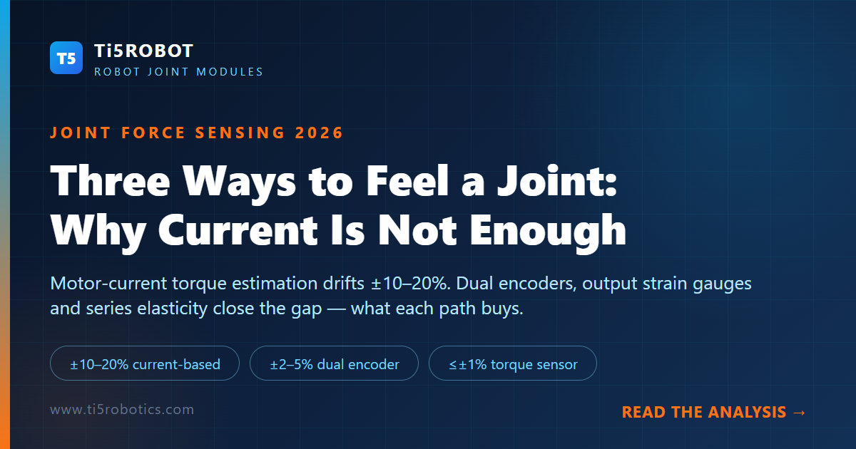
Every electric robot joint already contains one free torque estimate: motor current. Yet across published industry guides and engineering references in 2026, current-based force estimation still lands at ±10–20% of rated torque — too coarse for assembly, compliance, or safe human contact. This article walks through the three sensing paths engineers actually choose between, why the free signal fails, and what the latest integrated joint modules are now achieving at the output flange.
If you ask a robot joint "how hard are you pushing?", there are only three honest ways to get an answer. You can infer torque from the motor's electrical signature, read the transmission's elastic twist with two encoders, or measure the load directly with a strain-gauged element at the output. Everything else in joint force control — collision detection, lead-through teaching, impedance control, delicate assembly — is built on choosing between these three paths and living with their trade-offs. In 2026 the choice has become urgent: humanoid robot actuators are moving from staged demonstrations into real physical work, where friction, contact, and error are not edge cases but the daily operating condition.
The Free Signal That Lies: τ = Kt·Iq·N and Its Blind Spots
The default approach costs nothing extra. Motor torque is proportional to quadrature current: τ = Kt × Iq, and through a gear ratio N, joint torque follows. The signal is available at tens of kilohertz inside the drive, and for gross functions — overcurrent protection, trend monitoring, rough collision flags — it is genuinely adequate.
The problem is everything that stands between the motor's electromagnetic torque and the torque actually delivered at the joint output:
- Friction is nonlinear and state-dependent. High-ratio transmissions (typically 50:1 to 120:1 in harmonic-based joints) exhibit static friction with Stribeck behavior plus viscous terms that shift with input velocity and lubricant temperature. The efficiency of a harmonic drive is also direction-dependent: it differs between driving the load and back-driving it.
- The flexspline stores energy the motor cannot see. The thin-walled flexspline of a harmonic reducer flexes elastically under load, twisting slightly and releasing that energy later. This hysteresis is invisible to motor-side current measurement entirely.
- The torque constant itself drifts. Magnet flux falls as the motor warms, so the same current produces less torque. Published troubleshooting references list "torque per amp falls as the motor heats" as a first-order error source, distinguishable from alignment or friction errors precisely because it tracks winding temperature and recovers on cool-down.
- Lubricant shifts the baseline. One 2026 industry guide published by a joint-module vendor measured grease viscosity changing by more than 40% as an internal module temperature moved from 25°C to 65°C during heavy duty cycles — enough to move the apparent torque baseline substantially.
Stack these effects and the numbers converge across independent sources: current-based estimation typically lands at ±10–20% of rated torque (one vendor's dynamometer measurements put it at ±12–20%), with hysteresis between accelerating and braking passes and further drift with temperature and wear. One engineering reference puts it bluntly: motor current is the most model-dependent number in the joint — a boundary condition, not a sensor. It bounds torque, reveals trends, and flags anomalies, but it should not close a force-control loop.
Path One: Dual Encoders Reading the Reducer's Twist
The first upgrade keeps the sensing purely positional. Mount one absolute encoder on the motor shaft and a second on the joint output, and the difference between the two readings is the transmission chain's elastic deflection — which maps to torque through a known stiffness.
The physics is simple and the arithmetic is checkable. A typical harmonic reducer's nominal backlash sits under 1 arcmin, but the torque information lives precisely in those small angular differences. A deflection of 0.5 arcmin at the output of a joint driving a 1-meter arm corresponds to about 0.15 mm of positional error at the end effector — unacceptable for precision assembly if unmodeled, and valuable signal if measured deliberately.
Across published Chinese and English engineering guides, the dual-encoder approach lands at ±2–5% torque accuracy — roughly an order of magnitude better than current estimation. Its constraints are structural:
- The transmission must actually be elastic enough to deflect measurably; a very stiff chain produces a very small signal.
- Accuracy is bounded by encoder resolution and by how well the stiffness model holds across temperature and load history.
- It is an indirect measurement — a model with two encoders feeding it — so calibration discipline matters as much as hardware.
The practical appeal is cost and integration: no sensor element in the load path, no extra wiring across the rotating joint, and both encoders are usually wanted anyway for the dual-feedback positioning accuracy that a lightweight integrated joint module advertises.
Path Two: Strain Gauges at the Output Flange
The direct instrument is a joint torque sensor: an elastic element machined into the transmission's output path — a spoked flexure, a slotted tube, a thin-walled section — instrumented with strain gauges in a full Wheatstone bridge. Torque loads the element, the element strains microscopically, and the bridge converts strain to voltage with sensitivity set by geometry and gauge factor.
Done properly, this is the accuracy ceiling of the three paths: published guides place direct output torque sensing at ±1% or better of full scale. A full bridge, correctly placed, cancels temperature effects to first order and rejects axial and bending loads by symmetry. On platforms that measure joint torque directly, momentum-based collision detection becomes a residual computation with clean statistics rather than a threshold on a model error.
The engineering realities that come with that fidelity:
- Cross-axis coupling. A bridge built for torque also responds, at percent level, to bending moments and shear — so a calibration matrix, not a single constant, must be applied, and recalibration is needed after overload events.
- Drift management. Gauge resistance and amplifier offsets wander with temperature, so practical systems run continuous zeroing strategies — for example, low-pass snapshots of the offset whenever the joint is known to be unloaded.
- Rotating-joint signal transfer. Excitation and signal must cross the rotating interface through slip rings or telemetry — an added component, cable fatigue point, and failure mode that one published project account spent two days debugging when a cable broke inside a continuously rotating joint.
This is the architecture that 2026's high-end integrated joints have converged on: one vendor guide describes a six-in-one module stacking frameless motor, reducer, FOC drive, dual 17-bit encoders, an output strain-gauge bridge, and a safety brake in a single 60–80 mm-class housing, with vendor-published figures of ±1.0–1.5% full-scale accuracy, torque-loop bandwidth up to the hundreds of hertz, sub-5-millisecond collision reaction, and a minimum detectable contact torque in the tenths of a newton-meter — figures that should be read as vendor measurements, but that describe where the integration frontier sits.
Path Three: Series Elasticity as the Sensor
The third path inverts the design instinct. Instead of making the transmission stiffer so torque is easier to infer, the series elastic actuator (SEA) — introduced by Pratt and Williamson in 1995 — deliberately inserts a known spring between gear and link and measures its deflection: τ = k(θmotor/N − θlink). Both angles are already measured by the dual encoders of Path One; the spring turns compliance itself into the sensor.
A worked example shows why the idea still matters. With a spring stiffness of 1,000 N·m/rad and encoder pairs resolving 0.01° (1.75 × 10⁻⁴ rad), torque resolution is k × Δθ ≈ 0.175 N·m — fine enough for whole-body force control with no gauge in the load path. The spring simultaneously provides shock tolerance for the gear teeth and lower environmental impedance for robots operating near people.
The trade-off is resonance. The spring plus the reflected link inertia forms an oscillator: with a 0.5 kg·m² reflected inertia, ω = √(k/J) ≈ 45 rad/s ≈ 7 Hz, so usable force-control bandwidth must sit below it unless the controller is deliberately shaped around the resonance. A stiffer spring raises bandwidth but coarsens torque resolution — the same fundamental stiffness-versus-sensitivity compromise that governs strain-gauge element design, just expressed in mechanical form.
What the 2026 Factory Floor Is Showing
These paths are no longer lab taxonomies; they are visible in production statistics and trade-fair disclosures this month:
- At the 2026 China International Industry Fair in Shanghai, one exhibitor's force-controlled integrated joint module was reported by multiple Chinese media outlets to resolve force changes of 0.02 N·m — described as roughly the weight of a single grain of rice — and to react to contact within one millisecond. Those figures come from the exhibitor's own disclosure, but they mark how far output-side force sensing has been pushed into compact integrated joints.
- A Chinese force-control arm manufacturer publicly marked the delivery of its 10,000th full-joint force-controlled humanoid arm, with more than 70 embodied-AI companies reported to be integrating force-controlled arms into their systems — scale that only makes sense if joint-level force sensing has become a dependable, manufacturable subsystem.
- Industry coverage of the same fair noted humanoid-specific harmonic reducers with halved weight and precision retention beyond 10,000 hours, and cycloidal units claiming 85%+ efficiency — reminder that the mechanical chain a force-sensing architecture depends on is itself being retooled for humanoid duty cycles.
The direction is consistent: force sensing is migrating from an external accessory to a structural property of the joint itself, integrated at the output flange where the load actually is. That migration also explains why the mechanical side — the reduction stage debate between direct drive and geared routes — increasingly assumes a sensing layer at the output as a given.
Matching the Path to the Mission
Selection guidance that recurs across the published guides: do not buy the ceiling by default. For path tracking and obstacle avoidance, well-identified current estimation is already sufficient; dual-encoder flex sensing covers most whole-body compliance work; reserve the output torque sensor for the applications that genuinely need certified contact-force performance. And pair the sensing decision with a thermal and duty-cycle one — inside sealed joint housings, continuous available torque commonly derates to 60–80% of the benchtop rating, and a force-control loop is only as good as the actuator's ability to hold its output while hot. We covered the sizing side of that trade in the duty-cycle argument for joint actuators and the four levers of joint power density; force sensing adds a third axis to the same selection grid.
The joint that cannot feel its own output is guessing. The 2026 generation of integrated joints stopped guessing — and the three paths above are the vocabulary that decision is written in.
Source: PlaPivot, "Integrated Torque Sensors in Robot Joints: 2026 Guide" (2026); SciXa, "Proprioception: How Robots Sense Their Own Movement from Within" (2026); b2bwiki 特种电机选型指南 (2026); kwkr.cn 机器人关节双编码器力矩感知 (2026-10-13); Industrial Monitor Direct knowledge base on current-based torque estimation; 金羊网/环球网/腾讯新闻 CIIF 2026 展会报道 (2026-10-12/13); 光明日报/中国新闻网 人形力控臂万台级交付报道 (2026-10-10/13); Pratt & Williamson, "Series Elastic Actuators" (1995).